HW Getting started
Hardware overview
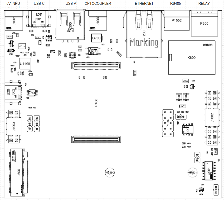
MAPIO hardware is based on multiple electronic boards to facilitate repair. It is based on a Raspberry Pi Compute Module 4, adding integrated circuits and connectors to enhance features.
PCB1 is mandatory, and provide the following functions :
Socket for Raspberry Pi Compute Module 4 (eMMC variants only)
Slot for an M.2 SSD (2242 or 2280)
Ethernet 1Gbps
1x USB-C 2.0
1x USB-A 2.0
Internal USB-C connector for debug purposes
Optocoupled UART input for TIC (Linky)
RS485 10 Mbps transceiver
250V 4A relay
5V Fan connector
Jumpers for power supply selection
Jumpers for Wifi/BLE/BOOT configuration
PCB2 is optional, but delivers the full potential of MAPIO :
A 18650 backup battery, providing several hours of autonomy in case of power loss
3 slots for (optional) RF modules
2.13” black and white ePaper
3 RGB LEDs
3 buttons
3V3 DC-DC converter
Mechanical overview
MAPIO has been designed to be installed on DIN rail. The case is a customized version of Bud DMB-4773.
You need to have at least 6 free spaces (108 mm) on your switchboard for MAPIO, plus space for AC-DC power supply. 7 free spaces are recommended.
Electrical specifications and installation
MAPIO has to be powered by a 5V DC, 2A power supply. The power input connector is on the upper left side of the casing.
You need to use the provided Wurth 691361100002 connector.
Connect the output of the AC-DC converter (for example, Mean Well HDR-15-5) to J1001 connector.
Note : the use of a 2A circuit breaker upstream of the AC-DC converter is highly recommended.
Jumper configurations
The main board has several configurations available. These configurations can be set by putting jumpers on the board headers.
Header |
Function |
|---|---|
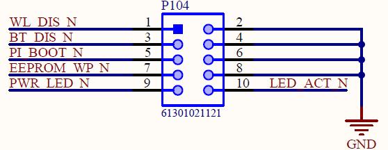
P104 |
Compute Module Configuration |
P901 |
RS485 120R Configuration |
P1003 |
5V Configuration |
P1005 |
3V3 Configuration |
Compute Module Configuration :
RS485 120R Configuration :
Connect a jumper on P901 if you want to enable 120R termination resistance for RS485. By default, the jumper is not mounted. The need for the termination resistance depends on your RS485 network.
5V Configuration :
This connector allows you to choose who provides the 5V Power supply :
Connect a jumper between mid-point and DC to power the 5V rail through upper left 5V IN connector (Default configuration)
Connect a jumper between mid-point and USB to power the 5V rail through J302 USB OTG connector
Please note :
Do not connect the three headers
When USB OTG power supply is enabled, U300 USB Switch disconnects the USB hub and connects J302 to the Compute Module. This is used when you want to flash the Compute Module.
3V3 Configuration :
This connector allows you to choose who provides the 3V3 Power supply :
Connect a jumper between mid-point and UPS to use the embedded regulator on PCB2 for the 3V3 source (Default configuration). Please note that you need to connect PCB2 to PCB1 before starting MAPIO.
Connect a jumper between mid-point and CM to use the Compute Module as the 3V3 source